StructuralEdgeConnection
Supports on 2D members edges
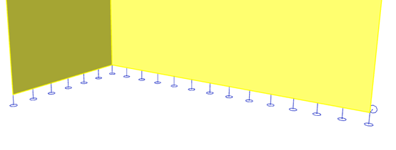
Object definition for a line support on a 2D member (StructuralSurfaceMember) edge. The support can be defined along the entire length of an edge or on its part only.
Specification in the excel
Column header |
Data type |
Example / enum definition |
Required |
Description |
|---|---|---|---|---|
Name |
String |
Sn6 |
yes |
Human readable unique name of the support |
Type |
Enum |
Fixed Hinged Sliding Custom |
no |
Type of constraint support in general. Has just informative value. Actual boundary conditions are set per transition/rotation per direction. |
Boundary condition |
Enum |
On edge On subregion edge On opening edge On internal edge |
yes |
Specifies on which type of object the force acts |
2D Member |
String |
S3 |
yes, if Boundary condition = On edge |
The name of a StructuralSurfaceMember the affected edge belongs to. |
2D Member Region |
String |
R1 |
yes, if Boundary condition action = On subregion edge |
The name of a StructuralSurfaceMemberRegion the affected edge belongs to. |
2D Member Opening |
String |
O1 |
yes, if Boundary condition action = On opening edge |
The name of a StructuralSurfaceMemberOpening the affected edge belongs to. |
Edge |
Integer |
1 |
yes, if Boundary condition = On edge, On subregion edge or On opening edge |
The index of edge of the surface member the load is applied to. The index starts with 1. The order is according to order of “edges” property at StructuralSurfaceMember, StructuralSurfaceMemberRegion or StructuralSurfaceMemberOpening |
Internal edge |
String |
ES2 |
yes, if Boundary condition = On internal edge |
The name of a StructuralCurveEdge the support is applied to. |
ux |
Enum |
Free Rigid Flexible Compression only Tension only |
yes |
Translation in X direction. Free - That is it imposes no constraint in the direction. Rigid - The connection in fully rigid in the specified direction. Flexible - The connection is flexible (elastic) in the specified direction. Parameter Flexible can be linear only, non-linearity is not supported. Compression only acts only under compression. If the support gets under tension it stops acting. Tension only support acts only under tension. See Notes for direction of tension and compression. |
uy |
Enum |
Free Rigid Flexible Compression only Tension only |
yes |
Translation in Y direction. Free - That is it imposes no constraint in the direction. Rigid - The connection in fully rigid in the specified direction. Flexible - The connection is flexible (elastic) in the specified direction. Parameter Flexible can be linear only, non-linearity is not supported. Compression only acts only under compression. If the support gets under tension it stops acting. Tension only support acts only under tension. See Notes for direction of tension and compression. |
uz |
Enum |
Free Rigid Flexible Compression only Tension only |
yes |
Translation in Z direction. Free - That is it imposes no constraint in the direction. Rigid - The connection in fully rigid in the specified direction. Flexible - The connection is flexible (elastic) in the specified direction. Parameter Flexible can be linear only, non-linearity is not supported. Compression only acts only under compression. If the support gets under tension it stops acting. Tension only support acts only under tension. See Notes for direction of tension and compression. |
fix |
Enum |
Free Rigid Flexible |
yes |
Rotational stiffness around X axis. Parameter Flexible can be linear only, non-linearity is not supported. |
fiy |
Enum |
Free Rigid Flexible |
yes |
Rotational stiffness around Y axis. Parameter Flexible can be linear only, non-linearity is not supported. |
fiz |
Enum |
Free Rigid Flexible |
yes |
Rotational stiffness around Z axis. Parameter Flexible can be linear only, non-linearity is not supported. |
Stiffness X [MN/m2] |
Double |
100 |
yes, if Translation X = Flexible |
The flexibility of the connection in X direction. Use this property only if the Translation X direction is Flexible. |
Stiffness Y [MN/m2] |
Double |
100 |
yes, if Translation Y = Flexible |
The flexibility of the connection in Y direction. Use this property only if the Translation Y direction is Flexible. |
Stiffness Z [MN/m2] |
Double |
100 |
yes, if Translation Z = Flexible |
The flexibility of the connection in Z direction. Use this property only if the Translation Z direction is Flexible. |
Stiffness Fix [MNm/rad/m] |
Double |
50 |
yes, if Rx = Flexible |
The flexibility in rotation of the connection around local X axis. Use this property only if the Rotational stiffness Rx is Flexible. |
Stiffness Fiy [MNm/rad/m] |
Double |
50 |
yes, if Ry = Flexible |
The flexibility in rotation of the connection around local Y axis. Use this property only if the Rotational stiffness Ry is Flexible. |
Stiffness Fiz [MNm/rad/m] |
Double |
50 |
yes, if Rz = Flexible |
The flexibility in rotation of the connection around local Z axis. Use this property only if the Rotational stiffness Rz is Flexible. |
Coordinate system |
Enum |
Global Local |
yes |
Defines the coordinate system of the member in which the support is applied. See Notes for more. |
Coordinate definition |
Enum |
Absolute Relative |
yes |
Selects the coordinate system that is used to define the length of the hinge. Relative means without units. For define length of the hinges in meters input absolute |
Origin |
Enum |
From start From end |
yes |
Specifies the origin of the coordinate system used for the definition of the length of the hinge |
Start point [m] |
Double |
value in meters for Coordinate definition = Absolute 0.0 value in percentage for Coordinate definition = Relative 0.0 |
yes |
Defines the position of the start point of the support in relative or absolute coordinates [m] |
End point [m] |
Double |
value in meters for Coordinate definition = Absolute 5.25 value in percentage for Coordinate definition = Relative 1.0 |
yes |
Defines the position of the end point of the support in relative or absolute coordinates [m] |
Parent ID |
String |
67b35d84-3d04-47aa-aa4a-dc1263982320 |
no |
Is filled for objects created by dividing curved geometry to series of straight line objects. To ensure successful round trip of segmented objects and their related objects, Parent ID needs to be present in both directions. |
Id |
String |
39f238a5-01d0-45cf-a2eb-958170fd4f39 |
no |
Unique attribute designation |
Notes
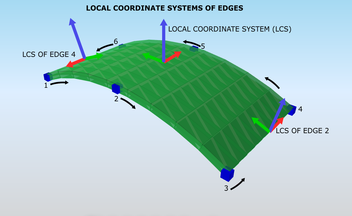
Line support on a 2D member can be defined by local or global coordinate systems. A local coordinate system is the coordinate system of the edge (not the coordinate system of the 2D member). As seen in the image below, the local coordinate system of an edge is created accordingly:
X-axis is in the direction of the line/curve of the edge. The direction is specified by the order of nodes in the StructuralSurfaceMember
Z-axis is parallel to the local Z-axis of the 2D member. For curved members local Z-axis is always perpendicular to the surface
Y-axis is tangential to the 2D member (it is in its plane) and the direction is set by the right-hand rule
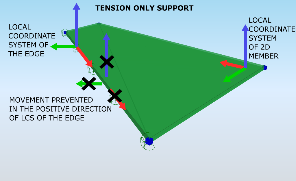
Tension and compression supports act only in a specific direction. Tension supports prevent the movement in the positive direction of an axis. Compression supports prevent the movement in the opposite direction. Those supports are compression only and tension only. See the image below for an example of tension only support using a local coordinate system. It prevents the movement only in the positive direction of the edge’s local axes.