RelConnectsRigidCross
Rigid Cross
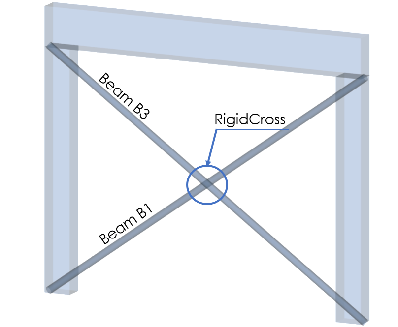
RigidCross is defining structural behavior of node (StructuralPointConnection), where two 1D elements (StructuralCurveMember) are being crossed. 1D members could be independent or dependency could be defined in following excel sheet. Rigid cross is often used for bracing of the structure.
Specification in the excel
Column header |
Data type |
Example / enum definition |
Required |
Description |
|---|---|---|---|---|
Name |
String |
RC1 |
yes |
Human readable unique name of the object |
1D Members |
String |
B1; B3 |
yes value from (StructuralCurveMember) |
The name from (StructuralCurveMember) Two 1D members should be defined |
Type |
Enum |
Fixed Hinged Custom |
no |
Constraint of the Rigid Cross The way the Rigid Cross acts in individual directions. Has informative character. When all constraints are set to Rigid = Fixed When all constraints are set to Free = Hinge Custom allows user defined behavior of Cross link and creating the Coupler |
u1 |
Enum |
Free Rigid Flexible Compression only Tension only Flexible compression only Flexible tension only Non linear |
yes |
Displacement of first connected member Free - That is it imposes no constraint in the direction. Rigid - The connection in fully rigid in the specified direction. Flexible - The connection is flexible (elastic) in the specified direction. Non linear - resistance in specified direction could be defined (Flexible) compression/tension only - acts rigid or flexible, only for defined strain (compression or tension) |
u2 |
Enum |
Free Rigid Flexible Compression only Tension only Flexible compression only Flexible tension only Non linear |
yes |
Displacement of second connected member Free - That is it imposes no constraint in the direction. Rigid - The connection in fully rigid in the specified direction. Flexible - The connection is flexible (elastic) in the specified direction. Non linear - resistance in specified direction could be defined (Flexible) compression/tension only - acts rigid or flexible, only for defined strain (compression or tension) |
u |
Enum |
Free Rigid Flexible Compression only Tension only Flexible compression only Flexible tension only Non linear |
yes |
Displacement of RigidCross Free - That is it imposes no constraint in the direction. Rigid - The connection in fully rigid in the specified direction. Flexible - The connection is flexible (elastic) in the specified direction. Non linear - resistance in specified direction could be defined (Flexible) compression/tension only - acts rigid or flexible, only for defined strain (compression or tension) |
fi1 |
Enum |
Free Rigid Flexible Non linear |
yes |
Rotation for the first connected member Free - That is it imposes no constraint in the direction. Rigid - The connection in fully rigid in the specified direction. Flexible - The connection is flexible (elastic) in the specified direction. Non linear - resistance in specified direction could be defined |
fi2 |
Enum |
Free Rigid Flexible Non linear |
yes |
Rotation for the second connected member Free - That is it imposes no constraint in the direction. Rigid - The connection in fully rigid in the specified direction. Flexible - The connection is flexible (elastic) in the specified direction. Non linear - resistance in specified direction could be defined |
fi |
Enum |
Free Rigid Flexible Non linear |
yes |
Rotation for the RigidCross Free - That is it imposes no constraint in the direction. Rigid - The connection in fully rigid in the specified direction. Flexible - The connection is flexible (elastic) in the specified direction. Non linear - resistance in specified direction could be defined |
Stiffness u1 [MN/m] |
Double |
3.0 |
yes, if u1 = Flexible, Flexible compression/tension only or Non linear |
The flexibility in direction of first member Use this property only if the u1 is set Flexible, Flexible compression/tension only or Non linear |
Resitance u1 [MN] |
Double |
0.20 |
yes, if u1 = Non linear |
The resistance in direction of first member Use this property only if the u1 is set Non linear |
Stiffness u2 [MN/m] |
Double |
3.0 |
yes, if u2 = Flexible, Flexible compression/tension only or Non linear |
The flexibility in direction of second member Use this property only if the u2 is set Flexible, Flexible compression/tension only or Non linear |
Resitance u2 [MN] |
Double |
0.20 |
yes, if u2 = Non linear |
The resistance in direction of second member Use this property only if the u2 is set Non linear |
Stiffness u [MN/m] |
Double |
5.0 |
yes, if u = Flexible, Flexible compression/tension only or Non linear |
The flexibility of the RigidCross Use this property only if the u is set Flexible, Flexible compression/tension only or Non linear |
Resitance u [MN] |
Double |
0.35 |
yes, if u = Non linear |
The resistance of the RigidCross Use this property only if the u is set Non linear |
Stiffness fi1 [MNm/rad] |
Double |
1.0 |
yes, if fi1 = Flexible or Non linear |
Torsional stiffness around the 1st member Use this property only if the fi1 is set Flexible or Non linear |
Resistance fi1 [MNm] |
Double |
0.05 |
yes, if fi1 = Non linear |
Torsional resistance around the 1st member Use this property only if the fi1 is set Non linear |
Stiffness fi2 [MNm/rad] |
Double |
1.0 |
yes, if fi2 = Flexible or Non linear |
Torsional stiffness around the 2st member Use this property only if the fi2 is set Flexible or Non linear |
Resistance fi2 [MNm] |
Double |
0.05 |
yes, if fi2 = Non linear |
Torsional resistance around the 2st member Use this property only if the fi2 is set Non linear |
Stiffness fi [MNm/rad] |
Double |
4.0 |
yes, if fi = Flexible or Non linear |
Torsional stiffness of the RigidCross Use this property only if the fi is set Flexible or Non linear |
Resistance fi [MNm] |
Double |
0.25 |
yes, if fi = Non linear |
Torsional resistance of the RigidCross Use this property only if the fi is set Non linear |
Parent ID |
String |
67b35d84-3d04-47aa-aa4a-dc1263982320 |
no |
Is filled for objects created be dividing curved geometry to series of straight line objects. To ensure successful round trip of segmented objects and their related objects, Parent ID needs to be present in both directions. |
Id |
String |
39f238a5-01d0-45cf-a2eb-958170fd4f39 |
no |
Unique attribute designation |
Notes
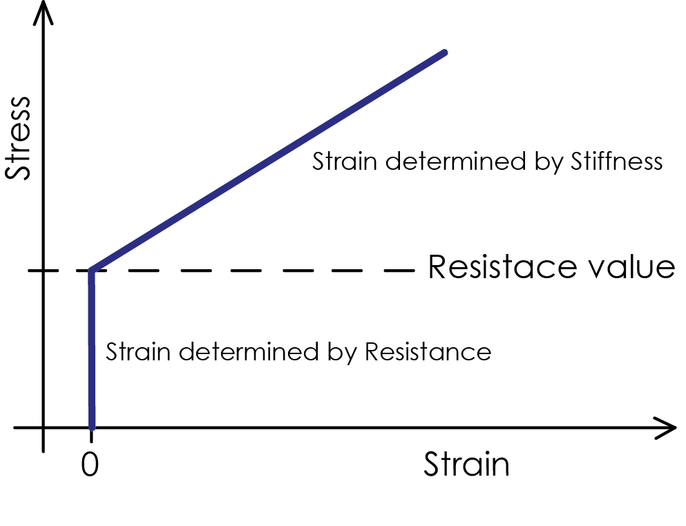
Resistance is defined by the value of maximal strain. Until is the value of maximal strain reached, Rigid cross acts fully rigid. After the value exceeded, RigidCross acts flexibly due to defined Value of Stiffness. This is how non linear behavior is achieved.
The axis of the connection is defined by the members of the RigidCross:
The first axis is assigned to the first member (i.e. the first member selected by the user during the definition of a new RigidCross - column “1D Members”).
The second axis is assigned to the second member (i.e. the second member selected by the user during the definition of a new RigidCross - column “1D Members”).
The third axis is perpendicular at the plane defined by member 1 and member 2.
Non linear behavior of material is handled with “Resistance”. The example is shown below.