StructuralSurfaceActionFree
Free surface load
Warning
object under development
The Free surface load is related to slabs. The load is not defined by the entity it acts on, but by a specific load border. Free loads are defined by means of “loading entities” that may overlap or affect one or more slabs.
Specification in the excel
Column header |
Data type |
Example / enum definition |
Required |
Description |
|---|---|---|---|---|
Name |
String |
FF1 |
yes |
Human readable unique name of the force |
Direction |
Enum |
X Y Z |
yes |
Specifies the base direction of the load |
Type |
String |
Standard |
no |
This property defines what the load is caused by, E.g. Standard, Wind, Snow, Self weight, Hoar Frost, Predefined, Plane Load, Water Pond, Water Pressure, Soil Pressure, Generated Water, Generated Soil |
Distribution |
Enum |
Uniform DirectionX DirectionY DirectionXY |
yes |
The load may be either constant across the slab or linearly variable ”DirectionX” and “DirectionY” enums are defining that, the value of the surface load is linearly variable according to the one of the user-selected axis ”DirectionXY” value inclination of surface load is defined in both directions well |
q [kN/m2] |
String |
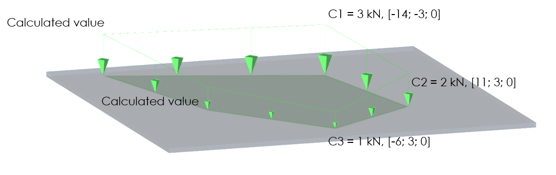
-10 (for “Distribution” set to “Uniform”) or C1:-5; C2:-7 (for “Distribution” set to “Direction*”) or C1:-3; C2:-2; C3:-1 (for “Distribution” set to “DirectionXY”) |
yes |
Specifies the size of the load in kiloNewtons per square meter. if Distribution is Direction X, Direction Y or Direction XY then the vertexes of the polygon of the free load have to be specified. For distribution Direction X and Direction Y two vertexes, for distribution in Direction XY, three vertexes. The format have to be following: C”number of vertex of the load polygon” : “value of the load in this vertex” The number of the vertex corresponds to the coordinate order. So the first coordinate means C1, the second C2 and so on For further understanding of “C” attributes see notes below table |
Load case |
String |
LC5 |
yes |
The name of the load case in StructuralLoadCase to which the force belongs |
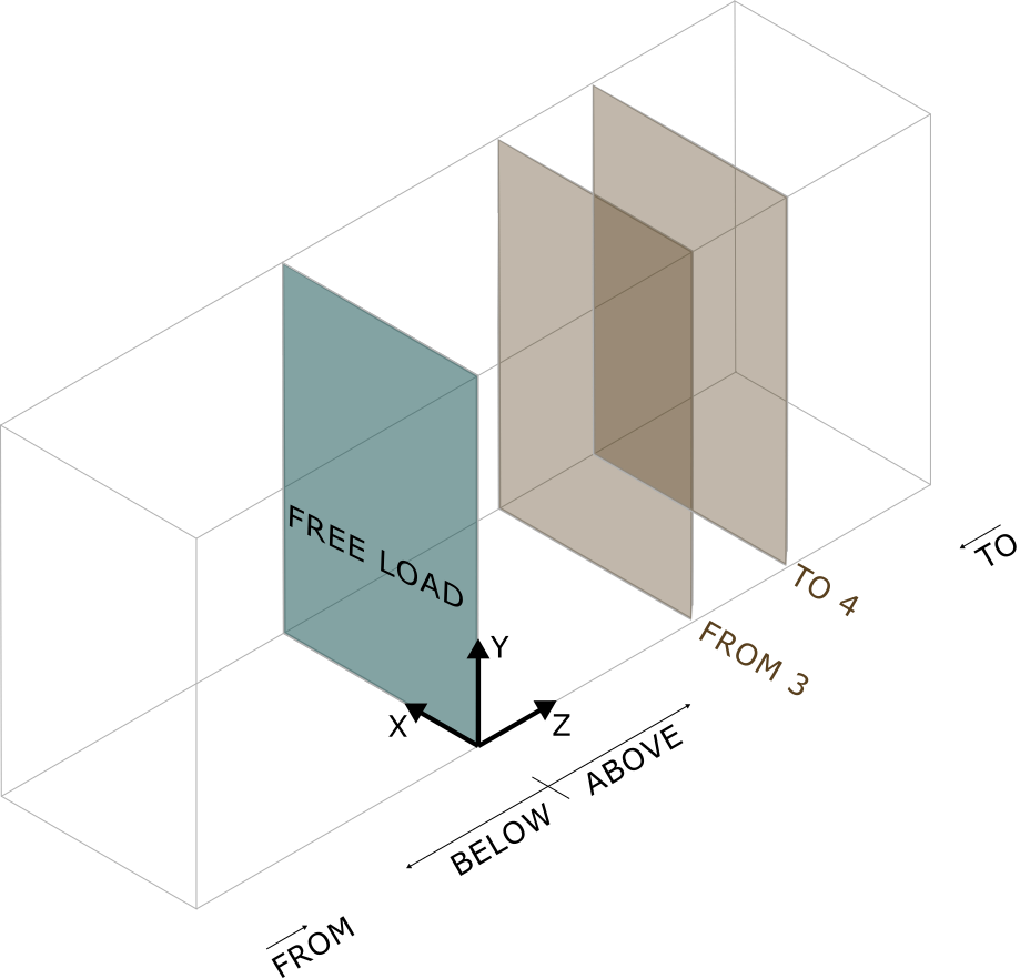
Validity |
Enum |
All, |
yes |
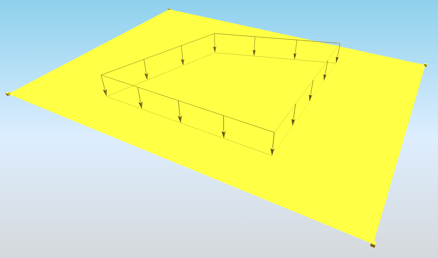
All = entities located above as well as below are subject to the defined load |
Validity from [m] |
Double |
-3.4 |
yes, if Validity = From to |
Validity in the direction of positive Z axis of the load. Load will be generated only above this distance |
Validity to [m] |
Double |
2.1 |
yes, if Validity = From to |
Validity in the direction of positive Z axis of the load. Loads will be generated only below this distance |
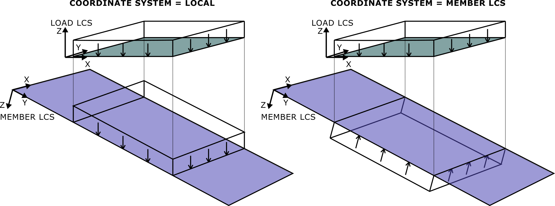
Local Z direction |
Enum |
Positive, |
yes |
Sets the direction of local Z axis of the load. Local Z axis is always perpendicular to the plane of the load. Positive means that the direction will be in the positive direction of global axis. For more information about the LCS of the load see notes |
Coordinate X [m] |
Double |
0.000; 2.050; 4.850; -2.000 |
yes |
The list of X coordinates of the nodes which define the geometry of the surface free load. Each coordinate is separated by semicolon and space. |
Coordinate Y [m] |
Double |
0.500; 1.050; 2.650; -1.500 |
yes |
The list of Y coordinates of the nodes which define the geometry of the surface free load. Each coordinate is separated by semicolon and space. |
Coordinate Z [m] |
Double |
0.000; 0.000; 0.000; 0.000 |
yes |
The list of Z coordinates of the nodes which define the geometry of the surface free load. Each coordinate is separated by semicolon and space. |
Edges |
String |
Line; Line; Line; Line |
yes |
Defines shape of the curve between two next nodes. Supported strings are: Line; Bezier; Circle arc; Parabolic arc; Spline. The names are separated by ; (semicolon) and space. |
Coordinate system |
Enum |
Global Local Member LCS |
yes |
Defines co-ordinate system of the member in which the load is applied |
Location |
Enum |
Length Projection |
yes |
Specifies whether the load is “put directly on an inclined 2D member” or whether the “projection on plan” is defined. |
Id |
String |
39f238a5-01d0-45cf-a2eb-958170fd4f39 |
no |
Unique attribute designation |
Notes
When is “Distribution” set to “DirectionX” or “DirectionY” the system is the same, but only two C values have to be defined.
When “Distribution” is set to “DirectionXY” is necessary to define 3 “C” vertexes. These Vertexes are defining projection onto slab and Value of the load as well. According to position and load value of “C” vertexes is load plane defined and every other vertex of the surface load is calculated. See example below.
The LCS of the load is created based on the order of the nodes defining the load. X axis is in the direction from the first point to the second. Z axis is always perpendicular, and the direction is set by the property Local Z direction. Y axis is then set by the right-hand rule.
Local Z direction = Positive means that local Z direction will be in the direction of positive global Z direction, if it is not possible then in the positive direction of global X axis, if that is also not possible then in the direction of positive global Y axis.
Above is in the direction of positive local Z axis from XY plane of the load or from defined distance from that plane. Below is in the direction of negative local Z axis. In the example below load will be generated only between 3 and 4 m from the free load.
The load is projected always in the direction perpendicular to the load = in the direction of local Z axis.