StructuralSurfaceMember
2D member (Plate, Wall…)
Instances of StructuralSurfaceMember describe face members, structural analysis idealizations of slabs, walls, shells. Surface members may be planar or curved with an arbitrary number of edges.
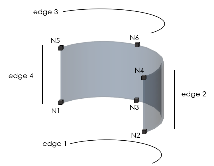
The geometry of a 2D member is defined by nodes (StructuralPointConnection)and edges. The edges define shape of the curve between two next nodes.
Specification in the excel
Column header |
Data type |
Example / enum definition |
Required |
Description |
|---|---|---|---|---|
Name |
String |
B1 |
yes |
Human readable unique name of the 2D member |
Type |
String |
Plate |
no |
The type of the 2D member, used within the model E.g. Plate, Wall, Shell. The type reflects the geometry or classification in the structure. Plate and Wall are expected to be planar (flat) geometry objects. Shell is expected to be non planar object. The type DOES NOT describes available internal forces for 2D finite element. |
Material |
String |
MAT_1 |
yes |
The name reference to the existing, valid name of the StructuralMaterial object. |
Thickness type |
Enum |
Constant Variable in global X Variable in global Y Variable in global Z Variable in local X Variable in local Y Variable in direction XY Variable radially |
yes |
Thickness of the slab can be defined as a constant - one thickness for whole 2D member or variable. Variability of the thickness can be defined in the global coordinate system (GCS) or in the local coordinate system (LCS) of the 2D member. For LCS are two more options: - Variable in two directions X and Y (three points have to be defined in thickness attribute ) - Variable radially, for circle slabs. Two points have to be defined, centre point and the point on the diameter. |
Thickness [mm] |
String |
200 N1:200; N2:250 |
yes |
The thickness of the structural surface member - For constant thickness: One number in millimetres (e.g. 200) - For variable thickness - type “Global X, Global Y, Global Z, Local X, Local Y and Radial: Two thicknesses in the following format N1:200; N2:250 . N1 means name of the existing StructuralPointConnection of the StructuralSurfaceMember and number is a thickness in this point. - For variable thickness type Direction XYThree thicknesses N1:200; N2:250; N3:280 have to be specified |
System plane at |
Enum |
Bottom Centre Top |
yes |
Defines the position of the system plane. |
Nodes |
String |
N81; N263; N659; N660 |
yes |
All nodes that belongs to surface member and defines its geometric shape. The names of the nodes are separated by ; (semicolon) and space. |
Internal nodes |
String |
N22; N23 |
no |
Internal nodes belonging to StructuralSurfaceMember defined in StructuralPointConnection Internal nodes are not geometry defining The names of the nodes are separated by ; (semicolon) and space |
Edges |
String |
Line; Line; Circular Arc; Line or Line;Spline-5;Line;Parabolic Arc;Line |
yes |
Defines the shape of the curve between two next nodes (or more nodes depends on edge type). Supported strings are: Line Circular Arc Circle by 3 points Circle and Point Parabolic arc Bezier Spline-x Where “x” number of nodes defining the spline The names are separated by ; (semicolon) and space. It is possible to also define circle geometry by using “Circle and Point” or “Circle by 3 points”. In case of “Circle and point” two nodes have to be defined, centre of the circle and a point on a circle. The circle defined by two points is always horizontal. |
Area [m2] |
Double |
2.359 |
no |
The value of the surface area of the StructuralSurfaceMember |
Layer |
String |
1st floor |
no |
Custom created layer. The layer can thus comprise entities that have something in common (e.g. one floor, columns of one floor, columns of the same length, etc.) |
LCS Type |
Enum |
x by vector y by vector Tilt of vector defined by point |
yes |
Defines type of the local coordinate system of the StructuralSurfaceMember. Option “Tilt of vector defined by point” allows change of orientation of the LCS to one point (for all mesh elements). For this, you have to specify coordinates of the vector. For further understanding see Introduction |
Coordinate X [m] |
Double |
1 |
yes |
Coordinate of the vector of the LCS in X direction |
Coordinate Y [m] |
Double |
0 |
yes |
Coordinate of the vector of the LCS in Y direction |
Coordinate Z [m] |
Double |
1,2 |
yes |
Coordinate of the vector of the LCS in Z direction |
LCS Rotation [deg] |
Double |
45.00 |
yes |
This value defines the rotation of local axes of the 2D member |
Structural Z Eccentricity [mm] |
Double |
-125 |
no |
Define the position difference between a physical element and its analytical member representation in Z direction (vertical movement of the center plane). Used to build up physical (structural body from analysis member). DO NOT affects internal forces. |
Analysis Z Eccentricity [mm] |
Double |
-125 |
yes |
Define the position difference between a physical element and its analytical member representation in Z direction (vertical movement of the center plane). Used to build up physical (structural body from analysis member). DO affects internal forces. |
Shape |
Enum |
Flat Curved |
no |
Specify the shape of the StructuralSurfaceMember in the sense of the planarity of the system plane. For Flat, all nodes have to be in the same plane. |
Behavior in analysis |
Enum |
Isotropic Orthotropic Membrane Press only |
yes |
Isotropic: A normal isotropic slab with identical properties in all directions is used. Orthotropic: An orthotropic slab with different properties in two orthogonal directions is used Membrane: Special membrane elements are used for the analysis of the slab (only normal forces allowed) Press only: Special elements capable of resisting only compression stress are used for the analysis of the slab (no tension allowed) |
Color |
String |
#7FFFFF00 |
no |
Defines the colour and transparency of the object. Colour is defined by Hex format #AARRGGBB. Transparency is controlled by the alpha channel AA. |
Parent ID |
String |
67b35d84-3d04-47aa-aa4a-dc1263982320 |
no |
Is filled for objects created be dividing curved geometry to series of straight line objects. Parent ID will ensure that curved edge is imported as straight parts to nonsupporting application, and back to original supporting application as curved geometry. To ensure successful round trip of segmented objects and their related objects, Parent ID needs to be present in both directions. |
Id |
String |
39f238a5-01d0-45cf-a2eb-958170fd4f39 |
no |
Unique attribute designation |
Notes
Rotation of LCS is measured from origin position of local x and y-axis and orientation follows positive rotation according to right-handed rule.
An example of a definition of a curved wall defined in the StructuralSurfaceMember sheet can be seen below, nodes N1, N2, N3 define the first arc and N4, N5, N6 define the second arc. Edges shown below are important for RelConnectsRigidMember: